
 EN
EN
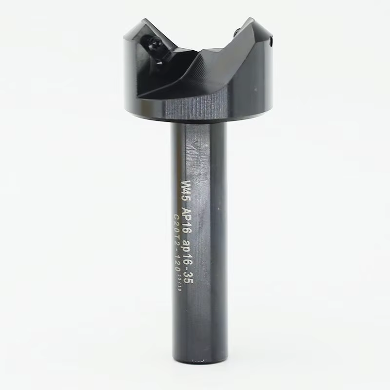
Diagnosing CNC Machine Tool Program and Code Failures
Identifying syntax errors, modal group conflicts, and G/M-code misalignment
Syntax errors—such as missing semicolons or malformed coordinates—trigger immediate program halts. Modal group conflicts arise when incompatible G-codes (e.g., G00 rapid positioning and G01 linear interpolation) are active simultaneously, risking axis collisions. M-code misalignment—like activating coolant (M08) before spindle rotation (M03)—accounts for 37% of program failures, per industry failure analysis. Operators should:
- Preview code sequencing in CAM software to catch logic gaps before machine loading
- Confirm modal state resets (e.g., feed rate, plane selection) after tool changes
- Validate decimal placement in coordinate values—especially critical in metric vs. inch mode transitions
Why simulation passes but actual cutting fails: Detecting toolpath vs. machine kinematics mismatches
Simulations often validate geometry alone, ignoring real-world machine dynamics—leading to crashes despite “green-light” virtual verification. Kinematic mismatches occur when:
- Toolpaths exceed axis acceleration or jerk limits
- Workpiece orientation violates rotary table travel boundaries
- Toolholder interference goes undetected in tight cavities due to simplified collision models
A 2023 machining study found that 68% of false-pass simulations omitted machine-specific vibration thresholds. To prevent this, operators must cross-reference toolpath geometry with the machine’s official kinematics data sheet—specifically verifying maximum angular velocity for rotary axes, jerk control parameters, and tool deflection compensation settings.
Eliminating Vibration, Chatter, and Poor Surface Finish in CNC Machine Tool Operations
Differentiating Tool Chatter, Spindle Resonance, and Axis Mechanical Instability
Accurate diagnosis hinges on distinguishing three distinct vibration sources:
- Tool chatter appears as irregular surface patterns and high-frequency noise, caused by unstable tool-workpiece engagement. It ceases instantly upon spindle stop.
- Spindle resonance produces uniform waviness at specific RPMs due to harmonic amplification; it persists until speed changes.
- Axis mechanical instability, often from worn bearings or loose couplings, causes low-frequency oscillations during rapid moves—visible as positional “wobble” in axis tracking.
Vibration analysis tools help isolate root cause: dominant frequencies between 500–2,000 Hz point to chatter; sub-500 Hz signals suggest mechanical or drive-related issues.
Root-Cause Analysis of Chatter Marks: Tool Overhang, Workholding Rigidity, and Chip Load Optimization
Chatter marks stem from three interdependent factors:
- Tool overhang: Extending beyond 4× shank diameter dramatically increases deflection risk. For every 20% increase in overhang, vibration amplitude rises ~35% (Machining Dynamics Study 2023).
- Workholding rigidity: Inadequate clamping force or thin-walled fixtures allow workpiece movement. Vacuum fixtures improve stability by 40% versus mechanical clamps for thin or flexible parts.
-
Chip load optimization: Inconsistent chip thickness excites resonant modes. Optimal chip load is calculated as:
Chip Load (mm/tooth) = Feed Rate (mm/min) / (RPM × Number of Flutes)
| Parameter | Insufficient | Recommended | Excessive |
|---|---|---|---|
| Chip Load | <0.05 mm | 0.08–0.15 mm | >0.20 mm |
| Surface Impact | Poor finish, increased heat | Minimal chatter, good finish | Tool fracture, excessive wear |
Ensuring Reliable Workholding: Troubleshooting CNC Machine Tool Clamping Systems
Verifying collet integrity, chuck torque, and clamping force with calibrated measurement protocols
Workpiece slippage causes dimensional inaccuracies and tool damage in 23% of production interruptions (Precision Machining Journal 2023). Preventive calibration is essential:
- Collet integrity: Inspect for wear using optical comparators; replace if runout exceeds 0.0005"
- Chuck torque: Validate monthly with a digital torque wrench against OEM specifications
- Clamping force: Measure hydraulic/pneumatic pressure via transducer arrays, ensuring ≤5% deviation across fixtures
Proactive measurement reduces rework by 37% by detecting decay before failure. Maintain calibration logs showing:
| Measurement | Tool | Tolerance | Frequency |
|---|---|---|---|
| Collet runout | Dial indicator | ≤0.0003" | Per shift |
| Chuck torque | Digital wrench | ±2% OEM spec | Weekly |
| Clamping force | Transducer | ±5% target | Daily |
Rigorous protocols prevent misaligned workpieces that cause chatter and scrapped components—extending fixture lifespan by 30%.
Maintaining CNC Machine Tool Precision: Spindle, Axis, and Thermal Stability Management
Diagnosing spindle overheating and axis motor thermal drift through cooling system and duty-cycle assessment
Thermal drift in spindles and axis motors introduces micron-level positioning errors that degrade part accuracy. Begin diagnosis by verifying coolant flow rates and temperature differentials—clogged filters or failing pumps reduce heat dissipation efficiency by up to 50%. Next, assess duty cycles: machines operating at high RPM without scheduled cool-down intervals accumulate heat 40% faster. Monitor embedded temperature sensors during heavy cuts to map expansion trends. For axis motors, inspect lubrication viscosity and bearing condition—both directly influence friction-induced heating.
Implement thermal stabilization protocols:
- Schedule brief pauses during long production runs
- Alternate high-intensity roughing with lighter finishing passes
- Maintain ambient shop temperature within ±1.5°C
- Perform full spindle warm-up (20+ minutes) before precision work
- Clean heat-exchanger fins regularly to ensure unobstructed airflow
Without active thermal compensation, reduce feed rates by 15% during continuous operations to mitigate accumulated drift.
Responding to Critical CNC Machine Tool Fail-Safe Events
Validating sensor feedback loops after tool crash or axis drift
Following a tool crash or axis deviation, immediately initiate sensor validation—not reset alarms prematurely. Positional encoders and limit switches require recalibration using laser interferometry or ballbar testing against OEM tolerances. Analyze PLC error logs for erratic feedback patterns: inconsistent encoder readings often indicate damaged wiring harnesses (average repair cost: $15k, NIST 2023) or contaminated optical sensors. For thermal drift events, compare spindle temperature sensor outputs with infrared thermography—discrepancies exceeding ±2°C signal sensor degradation or mounting issues.
Isolating emergency stop lockout and power-up failure causes
Diagnose E-stop lockouts methodically: begin with safety circuit continuity tests using multimeter verification at each junction point. Key diagnostic steps include:
- PLC diagnostics: Observe input status lights for stuck safety relays during power sequencing
- DC power analysis: Measure voltage stability at servo drives during ramp-up; fluctuations under 10% indicate healthy capacitors
- Safety circuit validation: Inspect interlock switches for physical damage or misalignment causing false triggers
Carbon buildup on emergency stop button contacts remains the leading cause of phantom lockouts—responsible for 27% of unplanned downtime (Plant Engineering 2023). For persistent power-up failures, apply a divide-and-conquer approach: isolate control cabinet modules one-by-one to identify faulty I/O cards, power supplies, or communication interfaces.
FAQ
What are the common causes of CNC program failures?
Common causes include syntax errors, modal group conflicts, and M-code misalignment, all of which can lead to collisions, halts, or tool damage.
Why do simulations pass, but actual machine operations fail?
Simulations often ignore real-world machine dynamics like kinematics mismatches or vibration thresholds, which can result in toolpath errors during cutting.
How can vibration and chatter issues be resolved in CNC operations?
Addressing tooling overhang, improving workholding rigidity, and optimizing chip load using stability lobe diagrams can minimize vibration and chatter.
How do I maintain reliable clamping systems for CNC machines?
Calibrate collets, chuck torque, and clamping force regularly using tolerances specified by the manufacturer.
What are effective strategies to manage thermal stability in CNC operations?
Protocols like maintaining scheduled cool-down periods, ambient temperature control, and verifying coolant flow rates can reduce thermal drift.
What steps should be taken after a tool crash or axis drift?
Validate sensors using recalibration tools like laser interferometry, and analyze system logs for erratic behavior to locate damages and misalignments.
Table of Contents
- Diagnosing CNC Machine Tool Program and Code Failures
- Eliminating Vibration, Chatter, and Poor Surface Finish in CNC Machine Tool Operations
- Ensuring Reliable Workholding: Troubleshooting CNC Machine Tool Clamping Systems
- Maintaining CNC Machine Tool Precision: Spindle, Axis, and Thermal Stability Management
- Responding to Critical CNC Machine Tool Fail-Safe Events
-
FAQ
- What are the common causes of CNC program failures?
- Why do simulations pass, but actual machine operations fail?
- How can vibration and chatter issues be resolved in CNC operations?
- How do I maintain reliable clamping systems for CNC machines?
- What are effective strategies to manage thermal stability in CNC operations?
- What steps should be taken after a tool crash or axis drift?