
 EN
EN
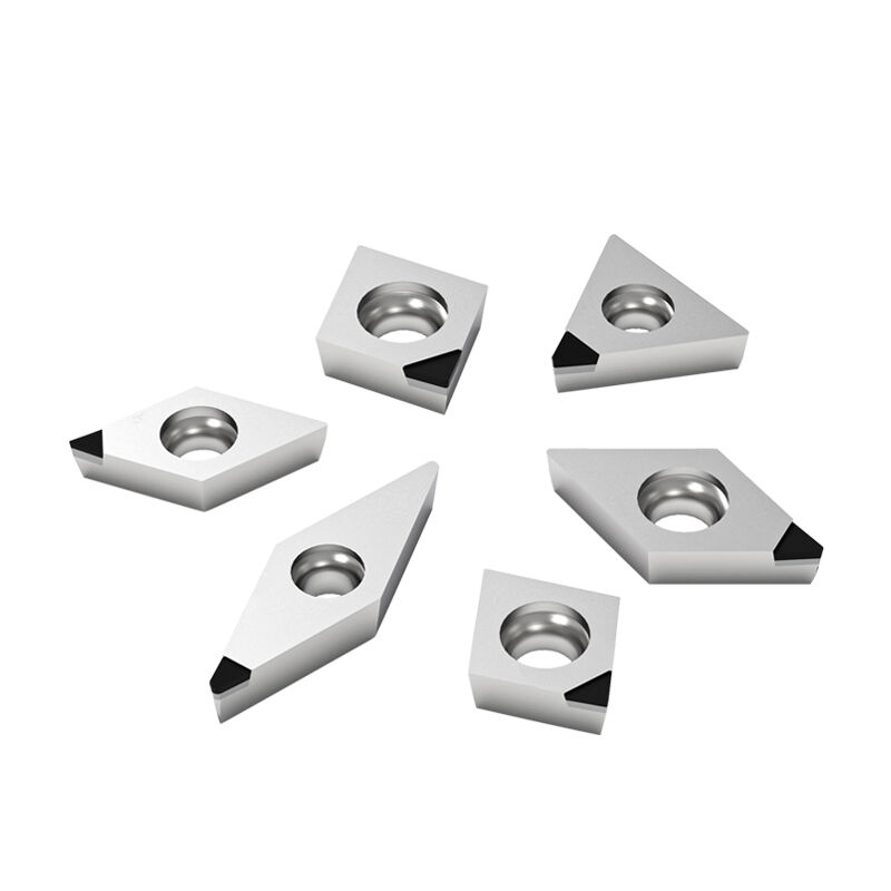
Core Turning Insert Shapes and Their Mechanical Impacts
How C-, R-, S-, and T-type shapes govern chip flow, edge strength, and vibration resistance
The geometry of turning inserts directly controls machining performance through three critical mechanisms. C-type inserts (80° diamond) excel in chip evacuation with their open point design, preventing built-up edge during continuous cuts. R-type (round) geometries distribute cutting forces evenly across the edge, enhancing vibration resistance in unstable setups by 30–40% compared to angular shapes. S-type (square) inserts provide maximum edge strength for heavy roughing but generate thicker chips requiring robust breakers. T-type (triangle) configurations balance accessibility and durability, making them ideal for threading operations where chip flow direction must align precisely with flank surfaces. Each shape establishes a distinct shear angle—directly influencing heat generation, tool life, and surface integrity.
Trade-offs: 75° C-type rigidity vs. round R-type for contouring and interrupted cuts
Selecting between common insert geometries involves balancing rigidity and adaptability. The 75° C-type offers superior edge stability for high-feed operations in hardened steels, reducing deflection by up to 25% versus rounded profiles. However, this rigidity compromises performance in interrupted cuts, where R-type inserts absorb impact forces through continuous edge engagement. For contouring complex profiles, R-types maintain consistent surface contact despite directional changes—while C-types risk chatter on curved paths. Manufacturers must prioritize either vibration control (R-type) or dimensional accuracy (C-type), based on workpiece geometry, machine rigidity, and cut continuity.
Rake Angle & Relief Geometry (M, ME, MD, E, D) for Cutting Force and Edge Durability
Positive vs. negative geometry: When to choose M-type for balanced steel turning or D-type for high-strength alloys
Rake angle governs cutting forces, heat generation, and edge resilience by shaping chip formation mechanics. Positive geometries reduce power consumption by up to 25% in softer materials like aluminum but sacrifice edge integrity under heavy loads. For carbon and alloy steel turning, M-type neutral geometries strike an optimal balance—maintaining 10°–15° rake angles that prevent workpiece hardening while sustaining edge stability. In contrast, D-type negative geometries (–5° to –15°) reinforce the cutting edge for high-strength alloys such as Inconel and titanium, trading higher cutting forces for up to 40% longer tool life under extreme thermal and mechanical stress. Relief angles further fine-tune friction and heat management: ≥15° relief minimizes heat buildup in gummy or stringy materials, while ≤8° relief prevents micro-chipping in hardened steels.
| Geometry | Rake Angle | Relief Angle | Best For | Edge Benefit |
|---|---|---|---|---|
| M-Type | Neutral (10°–15°) | Moderate (8°–12°) | Carbon/Alloy Steel | Balanced wear resistance and surface finish |
| D-Type | Negative (–5°– –15°) | Minimal (5°–8°) | High-temp alloys (e.g., Inconel, titanium) | Chip resistance and thermal stability under stress |
Use M-type inserts for continuous finishing passes in steel where vibration control and surface consistency are critical. Choose D-type for interrupted cuts in nickel-based superalloys at speeds exceeding 350 SFM—where edge reinforcement outweighs force efficiency.
Nose Radius, Entering Angle, and Wiper Geometries for Precision Surface Finish
How nose radius and wiper designs (–WFX, –WLR) reduce residual height and improve Ra values by up to 60%
Nose radius is the single most influential geometric parameter governing surface finish in turning. Larger radii (e.g., 0.031″ / 0.8 mm) spread cutting forces over broader contact zones, lowering peak stresses and reducing residual height—the primary contributor to surface roughness (Ra). This effect can improve Ra values by up to 60% compared to smaller radii—but oversized radii may induce chatter in slender or low-rigidity setups. Complementary entering angles between 45° and 95° optimize chip flow direction and minimize built-up edge, preserving finish integrity across varying feed rates and depths of cut.
For critical finishing applications, specialized wiper geometries like –WFX and –WLR incorporate secondary flats behind the main cutting edge. These features extend contact length without increasing radial force, effectively “polishing” the surface during the final pass. Independent testing confirms up to 60% lower Ra values versus standard inserts—eliminating secondary polishing steps while holding micron-level tolerances essential in aerospace, medical, and precision hydraulic components.
1 Ra: Surface Roughness Average
Matching Turning Insert Geometries to Specific Machining Operations
Geometry selection logic: Roughing (S/D + aggressive chipbreaker), finishing (C/WFX), threading (T), and grooving (R/MDR)
Optimal insert selection aligns geometry with operational intent—not just material. For roughing, S- or D-type inserts paired with aggressive chipbreakers maximize material removal rate while managing thick, hot chips; their negative rake and reinforced edges withstand high mechanical loads and thermal cycling. Finishing benefits from C-type inserts with wiper geometries (e.g., –WFX), which reduce residual height through extended edge contact and deliver mirror-like finishes in a single pass. Threading demands precise flank geometry and predictable chip flow—making T-type inserts the standard choice for maintaining thread profile fidelity and pitch accuracy. Grooving requires both radial clearance and edge toughness in confined spaces—R-type inserts with MDR (Multi-Directional Relief) provide the necessary combination of strength, chip evacuation, and vibration damping.
This strategic pairing ensures robust performance across the machining sequence: vibration-resistant roughing, high-fidelity finishing, repeatable threading, and reliable grooving—all anchored in fundamental geometric principles rather than rule-of-thumb assumptions.
FAQ
Q: What are the key differences between C-type and R-type inserts?
A: C-type inserts offer superior edge stability for high-feed operations, while R-type inserts enhance vibration resistance and surface contact adaptability, making them ideal for contouring and interrupted cuts.
Q: When should I use M-type vs. D-type rake geometries?
A: M-type neutral rake geometries are well-suited for carbon/alloy steel, balancing wear resistance and vibration control. D-type negative rakes are ideal for high-temperature alloys like Inconel and titanium, where chip resistance and thermal stability are critical.
Q: How does nose radius impact surface finish?
A: Larger nose radii reduce surface roughness by distributing cutting forces over a broader area, improving Ra values up to 60%. However, oversized radii may induce chatter in less rigid setups.
Q: What are wiper geometries, and how do they improve surface finish?
A: Wiper geometries like –WFX and –WLR incorporate secondary flats to extend edge contact, “polishing” the surface during finishing and reducing Ra values without additional polishing steps.
Q: Which inserts are best for roughing, finishing, threading, and grooving?
A: S- or D-type inserts with aggressive chipbreakers are best for roughing, C-type with wipers for finishing, T-type for threading, and R-type with MDR geometries for grooving.